







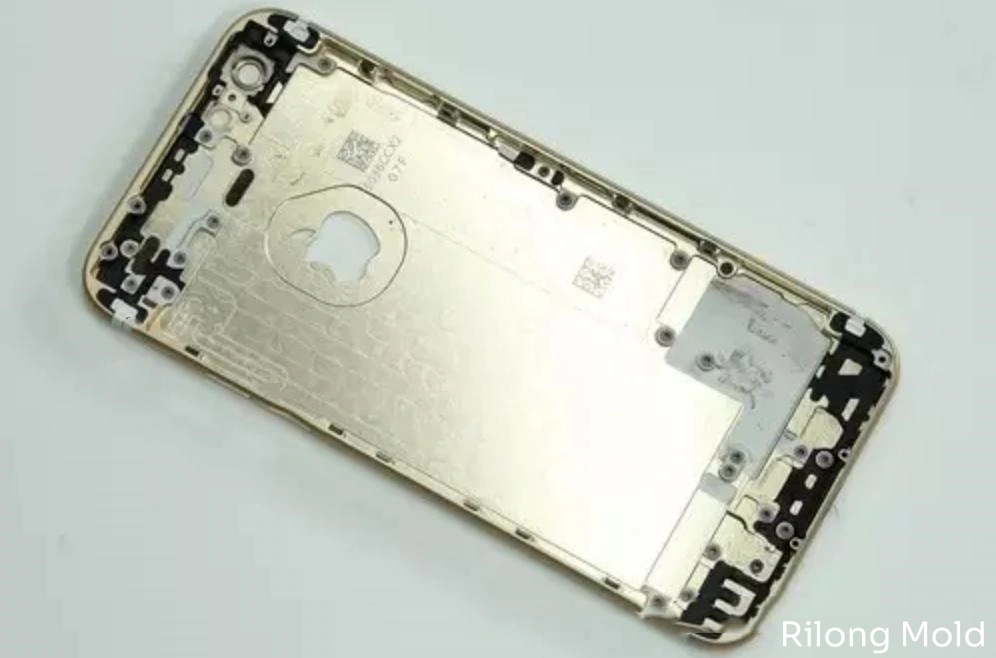
Nano injection molding is a metal-plastic direct joining process. A metal insert first receives a controlled micro- or nano-scale surface structure. During insert injection molding, molten engineering plastic enters that structure and solidifies, creating a strong integrated interface without a separate layer of structural adhesive.
The process is commonly called Nano Molding Technology (NMT). The proprietary NMT name is associated with Taisei Plas; the broader engineering category is also described as injection-molded direct joining (IMDJ). This distinction matters because “nano injection molding” is sometimes used incorrectly for nanoimprint molding, plastic microfeature replication, or metal injection molding—different processes with different equipment and objectives.
What Is Nano Injection Molding?
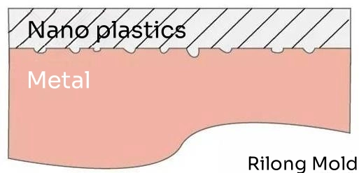
In conventional insert molding, plastic may be retained by holes, grooves, knurls, undercuts, or other macro-scale mechanical features. Nano injection molding adds a much finer surface architecture. The treated metal contains a large population of microscopic or nanoscopic cavities and irregularities. When the polymer melt wets and replicates these features, the solidified resin forms a dense network of anchors at the interface.
Mechanical interlocking is central to the joining mechanism. Depending on the metal, treatment, polymer, and interface chemistry, wetting and molecular or chemical interactions may also contribute. It is therefore too broad to claim that every NMT joint is “only physical” or “purely chemical.” The practical result must be established by tests on the exact material pair and process.
How Nano Molding Technology Works
1. Define the metal-plastic system
The process begins with the application, metal alloy, resin grade, joint geometry, expected loads, temperature, chemicals, sealing target, appearance, and service environment. A result obtained with one aluminum alloy and one glass-filled PBT grade cannot automatically be transferred to a different alloy, color, filler level, or polymer.
2. Manufacture and prepare the metal insert
The metal component may be machined, stamped, die-cast, extruded, or otherwise formed. Oils, oxides, release agents, polishing compounds, and contamination must be controlled. Edge geometry and dimensional tolerances also need to suit automated or manual loading into the mold.
3. Create the micro- or nano-scale surface
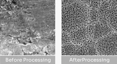
A controlled treatment creates a porous, roughened, or chemically modified surface in the intended joining zone. Commercial routes can use proprietary chemical treatments, anodic structures, laser texturing, or other material-specific methods. The treatment must be compatible with the alloy and must leave the non-bonding appearance and functional surfaces protected.
4. Control storage and handling
A treated surface can lose performance through contamination, corrosion, moisture, fingerprints, unsuitable packaging, or excessive storage time. The process plan should define packaging, shelf life, handling method, cleaning restrictions, and traceability from surface treatment to molding.
5. Load and locate the insert
The insert is placed in the mold and held against injection pressure without movement or deformation. Locators must control position while avoiding cosmetic damage, trapped air, unwanted heat loss, and over-constraint from metal thermal expansion. Insert temperature may be controlled where the validated process requires it.
6. Inject, pack, and cool the polymer
The polymer must reach and replicate the treated surface before the flow front freezes. Resin drying, melt temperature, insert and mold temperature, injection speed, cavity pressure, venting, packing, and residence time all influence the interface. More speed or pressure is not automatically better: excessive shear or thermal exposure can degrade a polymer, while insufficient energy can prevent complete replication.
7. Inspect and validate the joined part
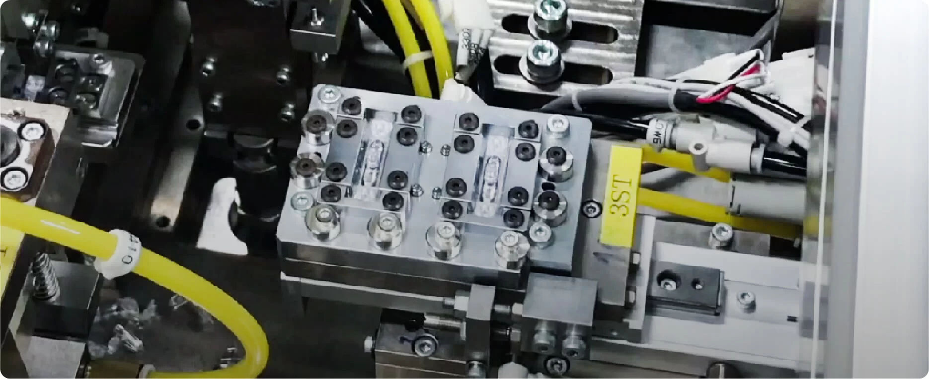
Visual acceptance alone is insufficient. Joint strength, sealing, dimensions, failure mode, thermal cycling, humidity, chemicals, impact, and product-specific loads may need evaluation. Process settings and surface-treatment lots should remain traceable so changes can be investigated.
Which Metals and Plastics Can Be Used?
Commercial NMT sources report treated combinations involving aluminum, magnesium, steel, stainless steel, titanium, and copper alloys, with engineering plastics such as PPS, PBT, and PA66. This is a feasibility range—not a promise that every alloy and every grade will bond equally.
| Material decision | Why it matters | Questions to verify |
|---|---|---|
| Metal alloy and temper | Surface chemistry, oxide behavior, treatment response, stiffness, and corrosion vary | Exact alloy? Heat treatment? Coating or cosmetic finish? |
| Surface treatment route | Controls pore or texture structure, cleanliness, wetting, and shelf life | Approved supplier? Treated area? Storage window? Lot traceability? |
| Polymer family | Crystallization, melt viscosity, temperature, shrinkage, and chemistry affect replication | PPS, PBT, PA, or another validated family? |
| Commercial resin grade | Flow, reinforcement, additives, color, and degradation stability are grade-specific | Manufacturer and grade? Filler percentage? Drying and processing limits? |
| Metal-plastic thermal mismatch | Temperature cycling creates interface stress | Operating range? Thermal cycles? Part geometry and constraint? |
| Service environment | Moisture, chemicals, galvanic conditions, and UV can change durability | Exposure media? Duration? Load during exposure? |
Glass fiber is often used in candidate engineering plastics to increase stiffness and adjust dimensional behavior, but it does not simply “match” metal expansion in every direction. Fiber orientation creates anisotropic shrinkage and thermal expansion. Gate location, flow direction, weld lines, and local fiber distribution therefore belong in the interface design. Our injection molding materials guide explains these grade-level differences.
Design Rules for Nano Injection Molded Parts
Design the joint around the load path
Interfaces generally tolerate shear and compression more favorably than concentrated peel. Increase effective joining area where possible, avoid sharp termination points, and spread load transitions. Do not use a published lap-shear value as a universal allowable stress for a product with peel, impact, fatigue, or thermal cycling.
Control polymer flow across the treated zone
The gate should support uniform filling and sufficient thermal energy at the interface without creating damaging jetting, trapped gas, excessive shear, or an unfavorable weld line. Flow length, wall thickness, fiber orientation, vent location, and cavity-pressure distribution must be evaluated together.
Keep metal inserts stable
Thin metal walls may move under injection pressure or distort during thermal cycling. The mold needs positive but non-damaging location, adequate support, controlled shut-offs, and a loading method that is repeatable at production rate. Molded features must not lock the insert into the wrong ejection direction.
Define sealing separately from joint strength
A joint can have good mechanical strength and still leak through a local void, untreated edge, weld line, or dimensional gap. If the part must resist air or liquid, specify pressure, medium, time, temperature, allowable leak rate, sample conditioning, and test coverage.
Plan cosmetic boundaries and corrosion protection
Masking, treatment boundaries, parting line, gate vestige, flash, and metal finish may all be visible. The design must also consider dissimilar-metal contact, exposed cut edges, moisture traps, cleaning chemicals, and whether later anodizing, painting, or plating is compatible with the joined assembly.
Benefits of Nano Injection Molding
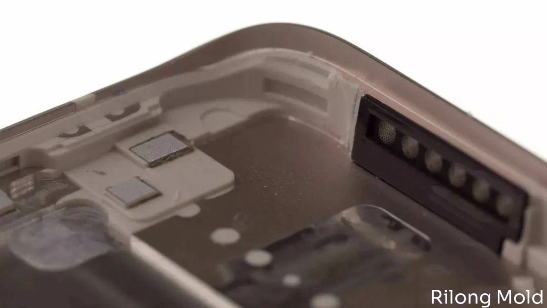
- Part integration: molded ribs, bosses, seals, insulating zones, and other functions can be added directly to a metal component.
- Reduced secondary assembly: a validated direct joint can reduce or eliminate separate adhesive dispensing, screws, clips, or welding in the joining zone.
- Thin and lightweight hybrid structures: metal can provide stiffness, heat spreading, shielding, or appearance while plastic supplies local geometry and electrical isolation.
- Design freedom: polymer can form complex internal features that would be expensive to machine into metal.
- Potential sealing performance: a continuous, well-replicated interface can support air- or liquid-sealing designs when verified by product-specific tests.
- Repeatable mass production: once surface treatment, insert handling, tooling, and molding are controlled, the joining operation can be integrated into a molding cycle.
The economic advantage is application-specific. NMT may reduce assembly steps, but it adds surface treatment, insert logistics, specialized validation, and process controls. A cost model should compare the complete production route and expected yield—not only molding cycle time.
Limitations and Risks
- Material-pair dependence: not every metal, surface treatment, and polymer grade is compatible.
- Surface sensitivity: contamination, storage, handling, corrosion, and treatment variation can reduce joint performance.
- Narrower process development: interface replication adds requirements beyond producing a visually complete plastic part.
- Thermal mismatch: differential expansion and shrinkage can load the joint during molding and service.
- Inspection challenge: an interface may look acceptable while containing local incomplete replication or weak regions.
- Repair and disassembly: a strong integrated joint is intentionally difficult to separate.
- Recycling complexity: eliminating adhesive may help some separation routes, but a metal-plastic hybrid is not automatically easy to recycle. Product architecture and end-of-life processing still matter.
- Intellectual-property and supplier scope: proprietary treatments and trade names require clear licensing, sourcing, and responsibility.
NMT vs. Other Metal-Plastic Joining Methods
| Method | Main joining principle | Advantages | Watch-outs |
|---|---|---|---|
| Nano injection molding / IMDJ | Polymer replicates treated micro/nano metal surface during insert molding | Direct integration, fine joint area, fewer assembly elements | Treatment, material pair, handling, process window, durability validation |
| Conventional insert molding | Plastic locks around holes, grooves, knurls, or undercuts | Simple concept, visible mechanical retention, broad material options | Needs space for macro features; stress concentration and leak paths |
| Structural adhesive | Adhesive layer bonds prepared surfaces | Joins many shapes and spreads load over area | Dispensing, cure, surface prep, thickness, aging, contamination |
| Screws, rivets, or clips | Discrete mechanical fastening | Serviceable and familiar; easy inspection | Added parts, assembly, local stress, space, possible leak paths |
| Plastic welding or heat staking | Thermal or mechanical deformation after molding | Useful for compatible plastic features and assemblies | Requires access and secondary equipment; not a direct metal-surface bond |
NMT is not automatically superior. The right choice depends on load direction, available joint area, sealing, appearance, serviceability, production volume, material compatibility, validation cost, and supply chain. Our insert molding and overmolding service page provides additional context for integrated components.
How to Test a Metal-Plastic NMT Joint
The ISO 19095 series provides a framework for evaluating adhesion-interface performance in plastic-metal assemblies. Depending on the part and risk, validation can include:
- Tensile and tensile-shear strength
- Peel, bending, impact, or product-specific loading
- Leak or sealing performance
- Thermal cycling and high/low-temperature aging
- Humidity, water, salt, oil, cleaners, or application chemicals
- Vibration, fatigue, drop, or shock testing
- Cross-section, microscopy, CT, or destructive failure analysis where appropriate
- Dimensional inspection before and after conditioning
Report failure mode as well as peak force. Cohesive failure in the polymer, interface separation, metal deformation, and mixed failure tell different engineering stories. Test specimen geometry, conditioned state, loading rate, environment, and treated lot must be documented to make results comparable.
Common NMT Defects and Their Causes
| Problem | Possible causes | Engineering response |
|---|---|---|
| Low or variable joint strength | Surface contamination, treatment variation, expired storage window, moisture, incomplete replication, polymer degradation | Audit surface lot and handling; verify drying; review interface temperature, fill, pressure, and residence time |
| Interface peel at an edge | Peel-dominant geometry, sharp termination, thermal stress, insufficient joining area | Redistribute load; soften transitions; expand treated area; reassess thermal cycling |
| Short fill or void at metal | Premature freezing, trapped air, poor gate location, insufficient venting | Review flow path, insert/mold temperature, gate and vent design, and process window |
| Insert movement or deformation | Weak support, excessive pressure imbalance, thin metal, poor loading repeatability | Improve location and support; balance filling; add presence/position detection |
| Flash at the insert boundary | Insert variation, damaged shut-off, inadequate support, excessive local pressure | Control insert tolerance; improve shut-off and support; maintain tooling |
| Leak despite acceptable strength | Local void, discontinuous treatment, weld line, edge path, dimensional gap | Map the sealing path; add part-specific leak testing; inspect local interface continuity |
| Warpage after molding or aging | Metal-plastic CTE mismatch, resin shrinkage, fiber orientation, uneven cooling | Use simulation and trials; adjust gate/cooling; revise geometry or material pair |
| Corrosion or discoloration | Residual chemistry, incompatible post-treatment, trapped moisture, galvanic environment | Review cleaning, rinsing, isolation, coatings, packaging, and exposure testing |
Applications of Nano Injection Molding
- Consumer electronics: metal housings with antenna windows, insulating zones, bosses, ribs, or local seals
- Automotive and mobility: lightweight structural-electrical hybrids, sensors, connectors, thermal-management parts, and housings
- Industrial equipment: rigid metal frames with directly molded guides, seals, covers, or electrical isolation
- Medical and laboratory products: selected hybrid housings or functional assemblies where the exact materials, cleaning, sterilization, and regulatory path are validated
- Communication devices: metal structures with controlled polymer regions for radio-frequency transmission
The process is especially attractive when a product genuinely benefits from both materials in one compact component. It is less compelling where a simple snap, screw, or conventional insert-molded undercut already meets the requirements at lower risk.
What to Include in an NMT Project RFQ
- 3D CAD, 2D drawing, and identification of treated and cosmetic zones
- Exact metal alloy, temper, manufacturing route, and finish
- Exact polymer manufacturer, grade, reinforcement, color, and regulatory requirements
- Joint loads, directions, safety factor, expected life, and failure consequences
- Temperature, humidity, chemicals, UV, vibration, impact, and cleaning exposure
- Sealing pressure, medium, allowable leak rate, and test method
- Appearance standard, treatment boundary, permissible gate and ejector marks
- Annual and lifetime volume, cavity target, automation level, and traceability needs
- Required prototype, coupon, trial, durability, and production-approval plan
- Responsibility for metal manufacture, surface treatment, molding, testing, and change control
A feasibility program should be agreed before production steel is finalized. This may include treated coupons, representative joint specimens, short-shot studies, interface sections, destructive tests, leak tests, and environmental conditioning.
Häufig gestellte Fragen
What does “nano” mean in nano injection molding?
It refers to the very fine surface structure created on the metal joining area. The product itself is not nanoscale. The treated structure gives molten polymer many small features to enter and anchor within during molding.
Is nano injection molding the same as metal injection molding?
No. Metal injection molding (MIM) injects a feedstock of metal powder and binder, followed by debinding and sintering to make a metal part. NMT joins an already solid metal insert to injected polymer.
Does NMT use adhesive?
The defining NMT route directly joins polymer to a treated metal surface during injection molding without a separate structural-adhesive layer. Some product designs may still use other coatings, seals, or assembly processes elsewhere.
Is an NMT joint waterproof?
It can support a sealed design, but it is not automatically waterproof. Interface continuity, joint geometry, material pair, molding conditions, treatment boundary, pressure, temperature, and aging all matter. The finished part needs a defined leak test and durability validation.
Is nano injection molding stronger than adhesive bonding?
Neither process is universally stronger. Performance depends on materials, surface preparation, joint geometry, load mode, environment, and manufacturing control. Compare representative specimens and product-level durability under the same requirements.
Is NMT environmentally friendly and recyclable?
Removing adhesive and reducing part count may benefit some products, but environmental impact depends on the surface-treatment chemistry, energy, yield, material sourcing, product life, and end-of-life separation. A metal-plastic hybrid should not be labeled recyclable without a defined recovery route.
Does nano injection molding require a special injection molding machine?
The defining requirement is controlled surface treatment and insert molding, not a universally smaller barrel. Machine selection depends on the resin, shot size, temperature, injection performance, insert handling, mold controls, and validated process window. Specialized automation or heating may be needed for a particular product.
From Feasibility to Stable Metal-Plastic Production
Nano injection molding can create compact, strong, and functional metal-plastic assemblies, but the interface cannot be engineered in isolation. Metal alloy, treatment, storage, resin grade, gate and vent design, insert support, thermal history, testing, and traceability form one production system.
For a metal-plastic integration project, Rilong Precision Mold can review part geometry, material requirements, insert location, mold design and tooling, injection molding, filling and cooling strategy, trial plan, and inspection requirements. Surface-treatment scope and material-pair validation should be confirmed for each program. To discuss feasibility, send our engineering team your drawings, material specifications, volumes, and joint requirements.
Technical references: Taisei Plas describes Nano Molding Technology as metal surface treatment followed by thermoplastic insert molding. ISO 19095-1 provides guidelines for evaluating adhesion-interface performance in plastic-metal assemblies; the ISO 19095 series covers specimens, test methods, and durability environments. A peer-reviewed study on PBT and nano-porous anodized aluminum direct joining shows why replication and injection conditions must be validated rather than assuming that higher injection speed always improves strength. The journal overview Nano Molding Technology Allows Direct Bonding between Metal and Plastic provides additional process background.