






模具设计与生产
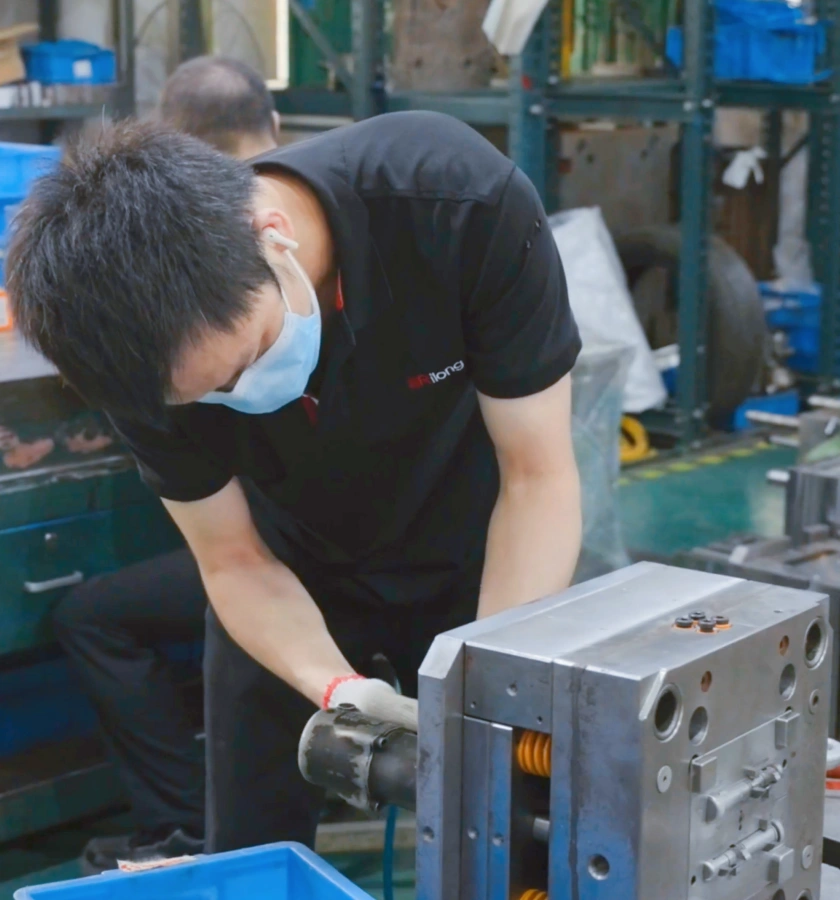
选择Rilong满足您的模具设计和制造需求
我们在广泛的市场上保持多样化的能力。我们专注于支持全球医疗保健、汽车、消费品和工业市场的模具项目。
多样化的模具结构
模具生产过程
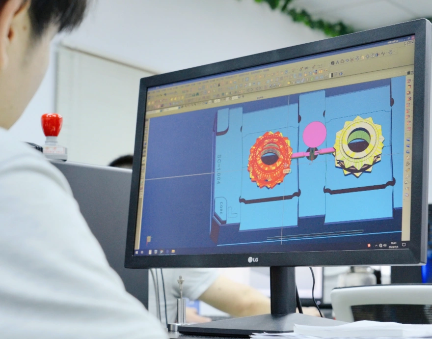
01
模具设计与准备
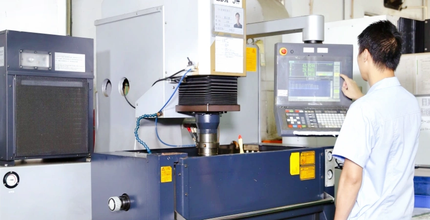
02
模具制造
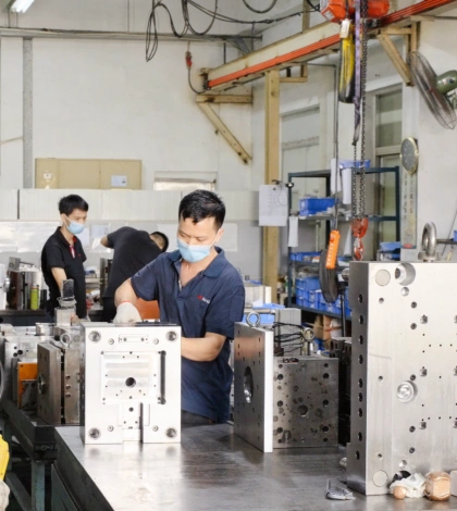
03
模具安装与测试
04
模具试模
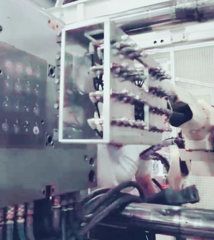
工装部生产设备
| 类别 | 编号 | 设备类别 | 品牌 | 数量 | 属性 | |||
| 转速表/车速表 | 精度 | MM | ||||||
| 加工设备 | 1 | CNC | ChaoQun | 1PCS | 8000/MIN | 0.01 | 850*650*900 | |
| Frank | 2PCS | 2.4W/MIN | 0.005 | 500*400*400 | ||||
| Seiki | 2PCS | 2.6W/MIN | 0.005 | 600*400*400 | ||||
| Charmilles | 1PCS | 1.4W/MIN | 0.005 | 850*650*400 | ||||
| 2 | Wire-cut machine | Wire-cut | SODICK | 1PC | 0.005 | 300*250*180 | ||
| Charmilles | 1PC | |||||||
| Speediness wire-cut | Jin Teng | 1PC | 500*400*350 | |||||
| YIGUANG | 1PCS | |||||||
| YIGUANG | 1PCS | |||||||
| 3 | EDM | SODICK | 1PCS | 0.005 | 500*400*200 | |||
| SODICK | 1PCS | 0.005 | 500*400*200 | |||||
| Charmilles | 2PCS | |||||||
| XingFeng | 3PCS | 0.01 | 600*500*300 | |||||
| TaiYi | 2PCS | |||||||
| 4 | Milling machine | DaYou | 4PCS | 5000/MIN | 0.02 | 800*500*120 | ||
| Heng yu | 2PCS | 5000/MIN | 0.02 | 800*500*120 | ||||
| 5 | Grinding machine | JianDe | 3PCS | 3600/MIN | 0.002 | 450*250*300 | ||
| Hangzhou machine | 1PCS | 3600/MIN | 0.002 | 450*250*300 | ||||
| YuQing | 2PCS | |||||||
| BaoCheng | 1PCS | 3600/MIN | 0.002 | 450*250*300 | ||||
| 6 | Grinding machine | Hangzhou machine | 1PCS | 1400/MIN | 0.002 | 400*1000*300 | ||
| 7 | Turning | XingYuan | 1PCS | 1600/MIN | 0.01 | 1500*300 | ||
Engineering Injection Molds for Stable, Repeatable Production
A production injection mold is more than a cavity that matches the CAD model. It is a manufacturing system that must fill, pack, cool and eject the part consistently while controlling wear, maintenance, cycle time and part quality. Rilong supports injection mold design and tooling from part DFM and mold concept development through machining, fitting, trial, correction and validation.
The tooling strategy is developed around the molded resin, part geometry, cosmetic standard, dimensional requirements, expected annual volume, target mold life and the machine on which the mold will run. This connects tool construction decisions to the real production requirement instead of treating every project as the same mold.
Injection Mold DFM: What We Review Before Cutting Steel
Early design-for-manufacturability review is the most economical time to reduce tooling risk. The review identifies features that can affect filling, cooling, ejection, appearance, tool strength or long-term maintenance. Recommendations are discussed against the part’s functional intent rather than applied as inflexible rules.
Wall Thickness and Transitions
Uniform walls and gradual transitions help reduce sink, voids, differential shrinkage and warpage. Thick local features may require coring, ribs or a revised packing strategy.
Draft, Shutoffs and Ejection
Draft is reviewed by surface texture and draw direction. Shutoff angles, lifters, slides and ejector locations are planned to release the part without drag marks, distortion or weak steel conditions.
Gate and Runner Strategy
Gate type and location influence weld lines, air traps, shear, packing balance, gate vestige and dimensional stability. Multi-cavity layouts also require balanced filling between cavities.
Parting Line and Cosmetic Surfaces
Parting lines, inserts and actions are positioned with appearance, flash control, machining access and serviceability in mind. Texture and polishing requirements are defined before steel finishing.
Cooling and Cycle-Time Risk
Cooling channels are arranged to remove heat as uniformly as the mold structure allows. Hot spots around deep cores, thick sections and slides can extend cycle time or create uneven shrinkage.
Tolerances and Measurement
Critical dimensions are reviewed for shrinkage sensitivity, mold construction, process capability and inspection method. Datums and acceptance requirements should be clear before tooling release.
Selecting the Right Mold Construction
The correct mold specification balances initial investment, cost per part, expected service life and maintenance. A prototype or bridge tool has different priorities from a high-volume multi-cavity production mold. The following decisions are defined for the individual program.
| Cavity strategy | Single-cavity, family or multi-cavity layouts selected according to demand, part balance, machine capacity, validation needs and production continuity. |
|---|---|
| Runner system | Cold runner, insulated runner or hot-runner solutions evaluated by resin, shot size, gate quality, scrap, cycle time, color changes, maintenance and program volume. |
| Core and cavity steel | Pre-hardened or hardened tool steels selected for cycle target, polish or texture, corrosion exposure, resin additives, wear and repair strategy. Abrasive glass-filled resins may require harder or replaceable wear areas. |
| Mold actions | Slides, lifters, collapsible cores, unscrewing systems or inserts used where geometry cannot release in the primary opening direction. |
| Ejection | Pins, sleeves, blades, stripper plates or air assist chosen around part stiffness, surface requirements, available contact area and reliable automatic operation. |
| Mold standard | DME, HASCO or specified regional/customer standards can be incorporated together with required locating, lifting, electrical, hydraulic and water-connection details. |
| Maintainability | Replaceable inserts, wear plates, standard components, access to water circuits and documented spare parts reduce downtime over the tool’s working life. |
Mold Flow, Cooling and Tool-Life Decisions
Mold-flow analysis can support decisions about filling pattern, pressure demand, weld-line position, air traps, gate balance, packing and likely warpage. It is most useful when the material data, part model, runner concept and process assumptions reflect the planned production conditions. Simulation guides engineering decisions, while mold trials confirm the behavior of the physical tool.
Cooling design is evaluated together with mold strength and manufacturability. Conventional drilled circuits, baffles, bubblers, high-conductivity inserts or conformal-cooling options may be considered where geometry and project economics justify them. Tool life is influenced by more than nominal shot count: resin abrasiveness, corrosion, molding pressure, slide travel, thin shutoffs, steel hardness, lubrication and preventive maintenance all matter.
Mold Trial, Validation and Production Release
- Design release: confirm the part revision, shrinkage assumption, cavity layout, mold action, runner and gate, cooling, ejection, mold standard and interface with the target molding machine.
- Tool manufacturing: machine and inspect mold base, cores, cavities, electrodes, inserts and actions; then complete heat treatment, finishing, fitting and assembly as specified.
- Initial mold trial: check tool movement and safety, establish filling and packing behavior, inspect ejection and appearance, and record the process conditions used for the samples.
- Correction and optimization: address steel-safe dimensions, flash, sticking, venting, cooling imbalance, gate appearance and other findings through controlled tool changes.
- Sample approval: provide molded samples and the agreed dimensional or first-article records for customer review. Critical dimensions should be evaluated under defined conditioning and measurement conditions.
- Release or transfer: prepare the approved tool for molding at Rilong or transfer, including agreed drawings, component information, trial records, spare parts and packing requirements.
Define Deliverables Before the Tool Build Starts
A clear tooling specification prevents uncertainty at approval and transfer. Depending on the program, deliverables can include the mold design, steel and component certificates, mold-flow report, trial parameters, sample parts, First Article Inspection or dimensional report, water-circuit diagram, electrical schematic, spare-parts list and tool-maintenance guidance. The required package should be agreed during quotation.
Rilong can combine tooling with custom plastic injection molding, overmolding and insert molding, two-shot injection molding, or LSR and rubber molding. Keeping tool design, trials and molding feedback connected helps engineering changes reach the correct part of the process.
What to Send for an Accurate Mold Tooling Quote
- 3D CAD model in STEP, X_T, PRT or SLDPRT format, plus the current 2D drawing where available.
- Resin grade, color, additives and any regulatory, optical, cosmetic or performance requirements.
- Critical dimensions, tolerances, texture or polish standard, gate restrictions and permitted witness marks.
- Expected annual volume, order quantity, target mold life and preferred cavity count.
- Required mold standard, hot-runner preference and receiving molding-machine specification for transfer tools.
- Sample approval, inspection, capability, documentation, spare-parts and delivery requirements.
Injection Mold Design and Tooling FAQ
What information is needed for an injection mold tooling quote?
Send the 3D CAD model, a 2D drawing with critical dimensions and tolerances, resin specification, expected annual volume, cosmetic requirements, target mold life, preferred mold standard, required validation documents, and the molding-machine specification when the tool will run at another facility.
How do you choose between a hot-runner and cold-runner mold?
The decision depends on resin behavior, part geometry, gate requirements, production volume, allowable runner waste, color-change frequency, maintenance capability and total program economics. The lowest tool price is not always the lowest cost per acceptable part.
What determines injection mold life?
Mold life depends on tool steel and hardness, resin abrasiveness or corrosion risk, part complexity, molding pressure, cycle count, cooling design, wear components, preventive maintenance, and the quality of machining and fitting.
What happens during an injection mold trial?
A mold trial checks filling, packing, cooling, ejection, dimensional stability, appearance and process repeatability. Results are used to identify tool corrections, establish a practical process window, and prepare samples and inspection records for approval.
Can Rilong build a mold for transfer to another molding facility?
Yes. Transfer tooling should be designed around the receiving facility requirements, including mold standard, machine platen and tie-bar limits, nozzle and locating-ring details, electrical and water connections, lifting provisions, documentation and spare parts.