Reverse Engineering Parts Using 3D Scanners and Software

Recreating parts or products without schematic diagrams or digital design files used to be daunting. Before the widespread application of 3D scanning technology, reverse engineering involved manually measuring objects to create drawings.

Today, everything has changed. Affordable 3D scanning technologies, more user-friendly software, and 3D printers enable rapid production of models, prototypes, and in many cases, final parts.

What is Reverse Engineering?

Reverse engineering is disassembling an object to understand how it works. Practically, reverse engineering involves measuring a physical object and then reconstructing it into a digital 3D model, which can then be 3D printed or manufactured in other ways.

In this article, we will guide you step-by-step through the process of turning a physical part into a final digital model and demonstrate key steps and major tool options in the entire process.

But first, let’s take a look at the applications of reverse engineering today.

Applications of Reverse Engineering

Re-manufacturing discontinued spare parts and tools is an obvious use of reverse engineering, but its applications go far beyond that.

Improving Old Parts and Products

Many companies still use molds that were created decades ago to manufacture parts, and the original designs and design decisions have been lost over time. With digital models, you can improve old parts to make them stronger or lighter. Perhaps the original design was created before the complex simulation and generative engineering software that exists today, which can virtually test stress responses and provide AI-driven improvements.

Aftermarket Customization

Especially in the automotive industry, providing products and accessories that fit perfectly with your new car is a big business. For this, manufacturers need precise measurements, and 3D scanning is the fastest method. You may not always manufacture these models, but 3D printing prototypes for fit and assembly testing is common.

Digitizing Handmade Prototypes

Artists, designers, and car manufacturers still shape concepts out of clay, but once the style is approved, it’s time to bring these products to production, starting with a digital model. After scanning and digitizing, these models can still be modified and stress-tested.

Product Investigation

Companies often reverse-engineer competitors’ products to understand their manufacturing processes, discover their strengths and weaknesses, and learn from their innovations. Of course, re-manufacturing products is subject to copyright, trademark, and intellectual property restrictions. Reverse engineering is also used to investigate incidents (such as car accidents) by 3D scanning the crashed vehicles and comparing the digital models with those of new cars.

The 3 Main Steps of Reverse Engineering

The reverse engineering process follows a standard workflow, which may vary slightly depending on the specific tools used and the desired results. Generally, the process involves the following steps:

  1. Data Collection: There are various methods for collecting dimensional data. The most common method today is 3D scanning, which we will explain in detail below.
  2. Data Processing: The data obtained from the 3D scanner is processed into a digital model. The raw 3D model usually requires some work to correct and refine areas that the scan may not have captured properly.
  3. Model Construction: The specific actions taken at this stage depend on the expected outcome of the reverse engineering process. If the goal is simply duplication, the part is ready for manufacturing. If repairs or additions are needed, the digital model is worked on in computer-aided design (CAD) software.

Obtaining Data Through 3D Scanning

Different types of 3D scanning technologies use different methods to capture data. They vary in size and cost, from handheld devices to large fixed systems. Each technology has its pros and cons and should be chosen based on the size and type of the object being scanned.

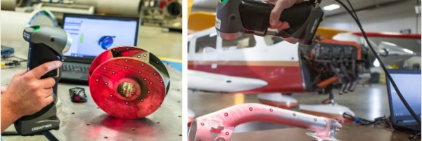
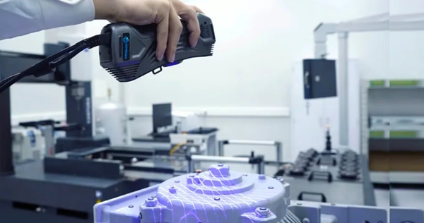
Reverse engineering typically uses optical 3D scanning (using structured light or laser beams). These scanners use light and sensor triangulation to collect laser reflection angles. With the distance between the scanner and the object, the scanning hardware maps the object’s surface and records points to form a 3D scan. 3D scanning can capture the exact position of millions of points on a part per second, generating vast amounts of data.

These optical 3D scanners are known for their precision, with resolutions as fine as several microns. However, their measurement range may be limited to just a few meters.

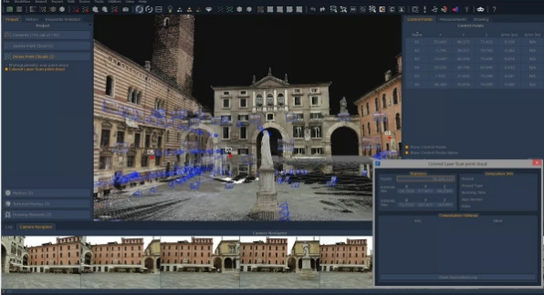
Photogrammetry is another 3D scanning technology that stitches together photos taken from different angles to create a three-dimensional object. This technique heavily relies on software, which processes hundreds of images to generate a 3D model. As smartphones become more powerful, photogrammetry is becoming more popular since photographing and processing can be done directly by hand.

While this new technology is great for creating digital color 3D models for online viewing, such as product images, the data obtained from smartphone apps is often insufficient for real reverse engineering, as the data may be too sparse or require more work in CAD programs.

Reverse Engineering Data Processing

Now that you have selected the best scanner for your application and budget and scanned your object, what’s the next step?

Unfortunately, the 3D scanner collects data points about the physical object; it does not create a digital model ready for direct manufacturing. There is a common misconception that optical 3D scanners output a digital model, but there is another software step between the scan data and a manufacturable model.

Popular CAD programs (such as Autodesk’s Fusion 360 or Dassault Systèmes’ Solidworks) cannot directly read raw data from a 3D scanner—they must be converted into models that these CAD systems can recognize and process. (Of course, Solidworks has a feature called ScanTo3D, but it is limited to handling low-resolution 3D scan data and is not suitable for reverse engineering.) Let’s break it down.

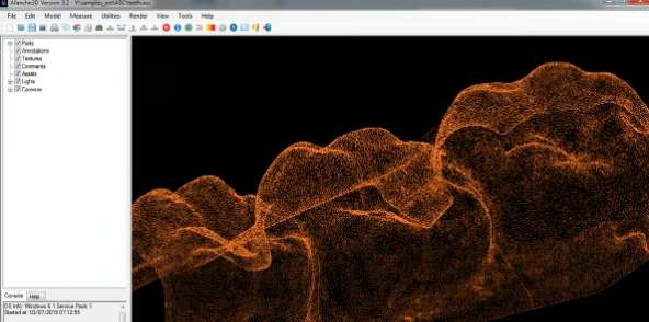
The more points there are in the “point cloud” (the raw scan data), the more accurate the model will be. High-quality scan data can save a lot of time in the CAD step. Low-resolution data may provide you with a rough outline of the part, but you’re essentially recreating the part from scratch. On the other hand, your application might not need all those points.

Mike Spray, owner of Laser Abilities, a 3D scanning service provider in Pontiac, Michigan, says, “You can always reduce the size of the point cloud by reducing the point spacing in the scanner software.”

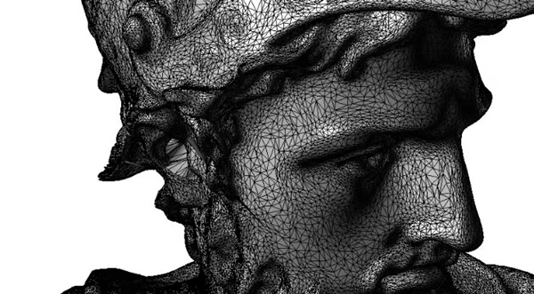
He explains that the software that comes with the scanner is the first place to begin editing the data. Once the point cloud is reduced, the scanning software can convert the point cloud into a model, also known as a 3D mesh, which consists of thousands to millions of tiny triangles or other polygons.

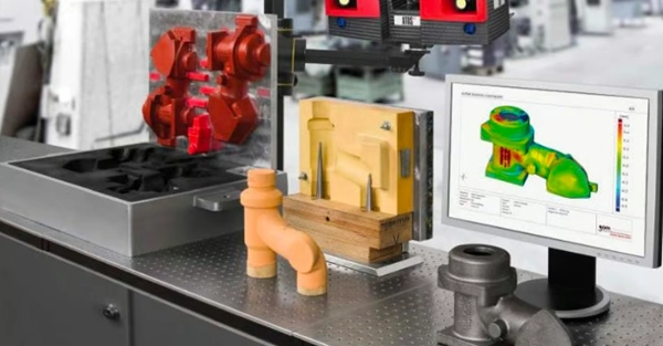
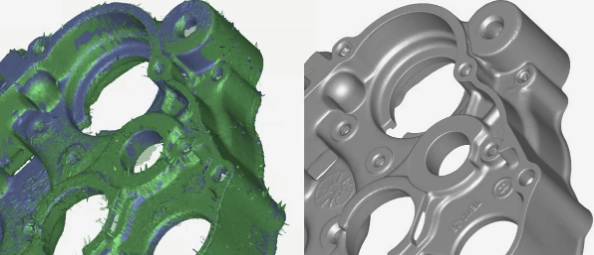
The software uses algorithms to “interpret” the point data and, in many cases, fills in gaps where the scanner did not capture enough data—such as when the surface is too shiny and interferes with the scanner’s light. This is where software vendors boast about the strength of their attribute algorithms and other “smart” features, designed to fix anomalies in the point cloud data. Check out the scan data below and the “cleaned up” model processed using Artec Studio software by 3D scanner manufacturer Artec 3D.

Some 3D scanner manufacturers, like Artec, Evixscan, Faro, and Zeiss, have developed sophisticated software that complements their hardware. While this software cannot fully replace CAD programs, it has made significant progress in converting scan data into CAD models. Other scanner manufacturers, like Evatronix, leave the interpretation step to third-party programs, such as the popular Geomagic. We’ll cover all these programs in the next section.

Spray adds, “Starting from a complete or ‘watertight’ mesh, you can move in different directions. The mesh can be exported directly as an STL file to the 3D printer’s slicing software. The mesh has no actual thickness, but it can be applied to the slicer.” From here, you just click “print” to create a physical replica of the object.

This mesh-to-slicing process is used to create an exact physical copy of the object. For example, you can use this method to print a product that will be used as a model to test its fit with another component.

However, for most reverse engineering projects, more steps are involved because the scanned product may need to be repaired or modified before manufacturing. Depending on the smoothness of data collection or the accuracy of the scanner, the model may need corrections, cleaning, refinement, or even some fine surface adjustments.

For example, to manufacture a tool, modifications are required based on the manufacturing method. “If you’re doing casting or injection molding, you need to add draft angles so the part can be released from the mold,” says Spray. “So, you may want to add a three or five-degree draft angle to the part. Your scan data won’t include that.” Similarly, some metal 3D printing methods require you to account for shrinkage during the manufacturing process.

Matching reverse engineering goals to software is not always straightforward. Often, the software that comes with the scanner is sufficient. Sometimes, using specialized programs created for editing scan data between the scanner and CAD programs can save a lot of time in the CAD process.

需要高质量注塑零件吗?

如果您有一个很棒的想法,我们可以帮助将其变为现实。我们以前做过这件事,并乐于在产品创造过程中成为合作伙伴。从在模具采购过程中为您提供建议,到将您的新产品交付给客户,我们希望在每一步都与您合作。

不断追求进步

我们的优势是我们的灵活性和适应性。我们结合我们的经验和您的想法,推出一步迈向未来的产品。

优质无缺陷生产

我们的愿景是不仅要交付超过客户期望的产品,还要通过与他们在模具设计领域的合作,帮助他们降低成本。 

准时交货 

我们迫切的希望客户能准时地收到货物,并确保在最短的时间内完成交付。