






التصنيع باستخدام الحاسب الآلي والطباعة ثلاثية الأبعاد
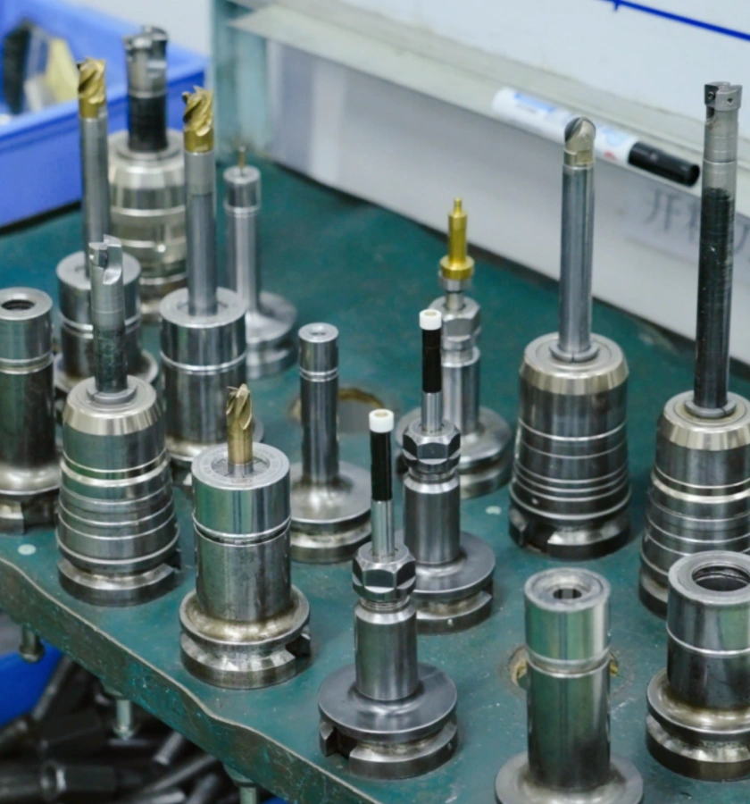
خدمات النماذج الأولية السريعة من ريلونغ
سواء كان الأمر يتعلق بمشكلة تصميم أو تطوير أو تصنيع، يمكننا تقديم حل هندسي لها.
خدمات النماذج الأولية السريعة عالية الجودة
مواد عملية CNC Milling
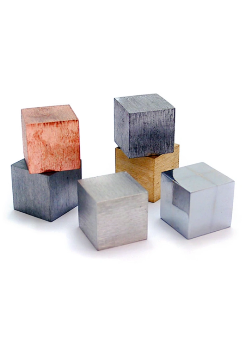
المواد المعدنية المدرجة أدناه مخصصة للـ CNC Milling. نقدم مواد معدنية عالية الجودة.
اختيار المواد المناسبة خطوة مهمة في عملية التصنيع. المواد البلاستيكية العامة المدرجة أدناه مخصصة للـ CNC Milling.
أحجام أجزاء CNC Milling
| الحجم | المتري(MM) | البوصة |
| الطول | 2500 | 98.4 |
| العرض | 2000 | 78.7 |
| الارتفاع | 1500 | 59 |
Precision CNC Machining for Production-Ready Parts
Successful CNC machining begins with more than selecting a machine and cutting material. Part geometry, datum strategy, tool access, workholding, material condition, tolerance, surface finish, inspection and production quantity all influence the machining plan. Rilong supports custom CNC parts from CAD and drawing review through milling or turning, inspection, finishing and delivery.
The objective is a stable process that produces acceptable parts repeatedly. Features that appear simple in CAD may require multiple orientations, custom fixtures, long-reach tools or special measurement. Reviewing these constraints before production helps control setup time, dimensional variation, tool marks and cost.
CNC Design for Machining: What Engineers Review
A machining DFM review connects the part design to tool geometry, machine movement and inspection access. Recommendations should protect the functional requirements while removing complexity that does not add value.
Tool Access and Setup Count
Every machined face must be reachable by a cutter and held securely. Features on many orientations may require indexed 4-axis or simultaneous 5-axis machining, additional setups or a revised design.
Internal Corners and Deep Cavities
Rotating cutters leave an internal radius. Larger corner radii allow stronger tools and more efficient cutting, while deep narrow pockets increase tool deflection, vibration and cycle time.
Thin Walls and Slender Features
Thin sections can move under cutting and clamping forces. Material, wall height, unsupported length, heat and toolpath strategy determine whether a feature can hold its intended form.
Threads, Holes and Edge Conditions
Standard drill and thread sizes improve tool availability. Hole depth, thread engagement, breakthrough, spotfaces, countersinks, chamfers and deburring requirements should be defined on the drawing.
Tolerances and Surface Finish
Tight tolerances and low roughness should be limited to functional surfaces. They may require finishing passes, controlled temperature, additional setups and more detailed inspection.
Datums and Inspection Access
A coherent datum system connects machining and measurement. Critical features need an inspection method that can reach the surface and reproduce the drawing’s alignment requirements.
Choosing the Appropriate CNC Process
Process selection depends on geometry, access, tolerance, quantity and the number of setups—not simply part size. One component may combine turning and milling, while another may be more economical as a near-net-shape part with only critical features machined.
| 3-axis CNC milling | Efficient for plates, brackets, housings, pockets and prismatic features that are accessible from planned orientations. |
|---|---|
| 4-axis CNC machining | Adds rotary indexing or continuous movement for features around a part, reducing manual repositioning and improving relationship between faces. |
| 5-axis CNC machining | Provides access to multiple faces and complex surfaces, often reducing setups for impellers, medical components, aerospace-style geometry and intricate prototypes. |
| CNC turning | Suited to rotational parts such as shafts, sleeves, bushings and threaded components; live tooling can add selected milled features where equipment and geometry allow. |
| CNC plus secondary operations | Grinding, EDM, heat treatment, anodizing, plating, painting, passivation or other processes can be planned where the drawing requires properties not produced by cutting alone. |
| 3D printing for prototypes | Useful for fast geometry evaluation or parts difficult to machine conventionally. CNC machining remains preferable where the project requires production material, machined accuracy, specific surfaces or established subtractive-process properties. |
CNC Tolerances and Surface Finish
The page lists machining capability down to 0.01 mm for suitable features, but a single tolerance cannot describe every part. Achievable results depend on nominal size, geometry, material stability, tool reach, setup count, wall stiffness, thermal effects, finishing and measurement uncertainty. Each critical characteristic should therefore be reviewed on the drawing.
General dimensions should use practical tolerances, while tighter controls are assigned only to fits, sealing surfaces, alignment features and other functional characteristics. Surface roughness should also be specified where it affects friction, sealing, appearance, coating adhesion or fatigue. Undefined cosmetic expectations can cause disagreement even when dimensions pass inspection.
Material Selection for Machined Parts
Material selection influences strength, weight, corrosion resistance, temperature performance, electrical behavior, machinability, dimensional stability, finish and price. Aluminum is often selected for low weight and efficient machining; stainless steel for corrosion resistance; alloy and tool steels for strength or wear; brass and copper for electrical, thermal or low-friction requirements; and titanium where strength-to-weight ratio and corrosion performance justify the added machining cost.
Engineering plastics such as POM, nylon, PTFE and UHMWPE require different workholding and thermal strategies from metals. Moisture absorption, residual stress, thermal expansion, creep and burr formation can affect final dimensions. Material grade, temper or condition should be stated rather than using only a broad family name.
Inspection Planning and Quality Documentation
Inspection begins with a readable drawing and agreed acceptance criteria. The control plan should identify critical dimensions, datums, threads, surface finish, sampling level and required records. Depending on feature type and accuracy, inspection may use calibrated hand tools, gauges, height measurement, optical equipment or coordinate measurement.
- Drawing review: confirm units, revision, projection, datums, geometric controls, material and finish.
- First-piece verification: check the initial setup before releasing the full quantity.
- In-process control: monitor tool wear and dimensions that can drift during machining.
- Final inspection: verify the agreed features after machining and applicable finishing.
- Documentation: provide dimensional, material or finishing records when defined in the quotation and purchase requirements.
What to Send for an Accurate CNC Machining Quote
- A 3D model in STEP, X_T, PRT or SLDPRT format and the current 2D production drawing.
- Material grade and condition, including temper, hardness or certification requirements.
- Quantity, repeat-order expectation and requested delivery schedule.
- Critical tolerances, datums, threads, fits, surface roughness and cosmetic requirements.
- Heat treatment, anodizing, plating, passivation, painting, marking or other secondary operations.
- Inspection sampling, dimensional reports, certificates, packaging and delivery destination.
For adjacent manufacturing needs, explore injection mold design and tooling, custom plastic injection molding, overmolding and insert molding, and LSR and rubber molding.
CNC Machining FAQ
What files are needed for a CNC machining quote?
Send a 3D CAD model such as STEP or X_T and a 2D drawing that defines critical dimensions, tolerances, threads, datums, surface finish, material, quantity, inspection requirements, and any required coating or treatment.
What tolerances can CNC machining achieve?
Achievable tolerance depends on feature size and geometry, material, machine access, setup count, thermal stability, finishing and inspection method. The page lists capability down to 0.01 mm for suitable features, but every critical tolerance should be reviewed against the drawing.
When should a part use 3-axis, 4-axis or 5-axis CNC machining?
Three-axis machining is efficient for accessible prismatic geometry. Four-axis machining supports indexed or continuous work around a rotary axis. Five-axis machining improves access to multiple faces and complex surfaces and can reduce setups when geometry, tolerance and volume justify it.
Which metals and plastics can be CNC machined?
Common options include aluminum, stainless steel, mild and alloy steel, brass, copper, titanium, tool steel, ABS, nylon, POM, PTFE, PE, PP, PVC and UHMWPE. Final selection depends on mechanical, thermal, chemical, cosmetic, regulatory and cost requirements.
How are CNC machined parts inspected?
Inspection is planned from the drawing and can include calibrated hand tools, gauges, height measurement, optical methods or coordinate measurement as appropriate. Critical features, datums, sampling level and required reports should be agreed before production.
From CAD Model to Precision-Machined Parts
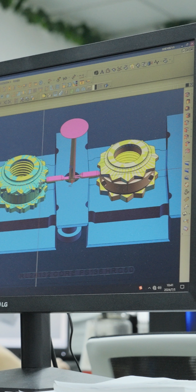
التصميم
Our engineering team reviews CAD models, drawings, tolerances, material requirements, surface finishes, and inspection needs before machining begins.
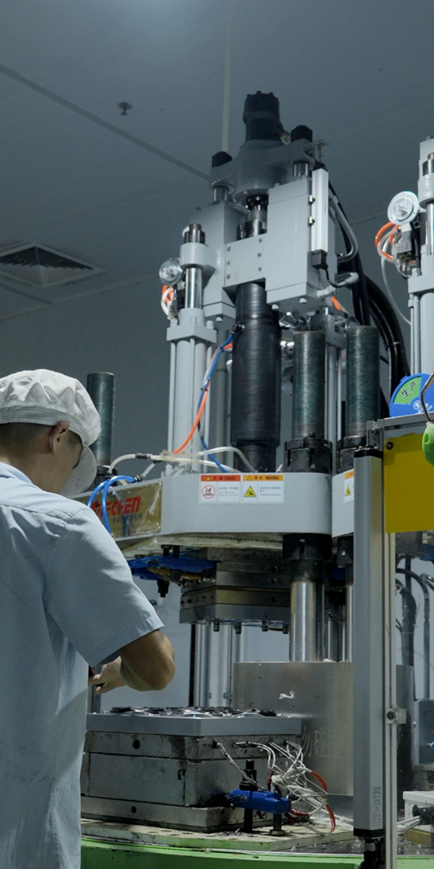
التصنيع
CNC milling, turning, and supporting prototype processes are planned around part geometry, tolerance, material, quantity, and required inspection records.

التنفيذ
After machining, parts can proceed through specified finishing, dimensional inspection, protective packaging, and shipment to the delivery destination.