






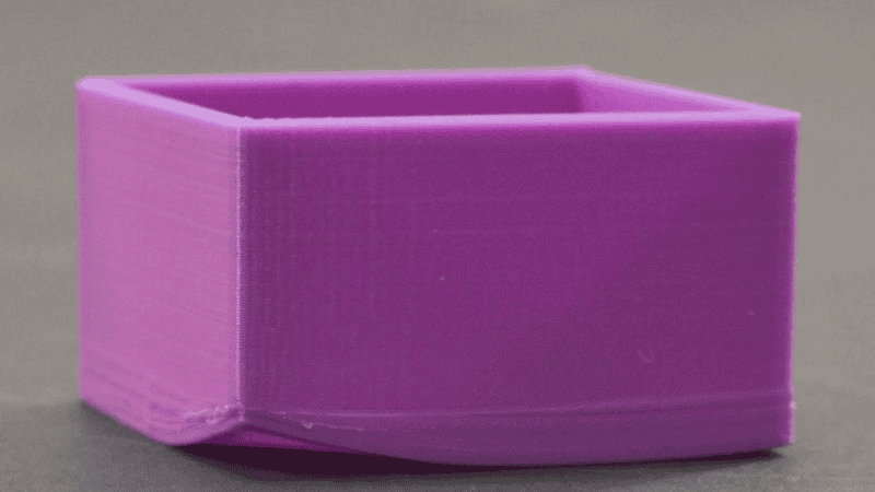

A flat panel bows after molding. Is the runner layout to blame—or is the part shrinking unevenly? The answer matters because these two defects demand completely different corrections. Changing a runner to solve thermal bowing wastes toolroom time; tuning cooling to solve a multi-cavity fill imbalance does the same.
This guide separates central flat-surface injection molding warpage from the runner phenomenon commonly called the corner effect. It also explains a terminology trap: some simulation software uses “corner effects” as a category of part warpage, while molders often use “corner effect” to describe shear-induced imbalance after runner turns. Always define the observed symptom before debating the name.
The short answer
| What you observe | Most likely mechanism | Where to investigate first |
|---|---|---|
| A single flat part domes or dishes after ejection | Differential cooling, differential shrinkage, molecular/fiber orientation, or structural buckling | Part geometry, cooling, gate seal, packing and material behavior |
| Nominally identical cavities fill at different rates after runner turns | Shear-induced melt-temperature and viscosity imbalance in the runner | Cold-runner branching, turn sequence, shear history and cavity pressure |
| Several cavities show different amounts of bowing | Both mechanisms may be present | First separate cavity-to-cavity filling from within-part warpage |
They are not the same failure mode, but they can coexist. A runner imbalance can change the pressure history delivered to each cavity, and that pressure difference can change shrinkage and final flatness. The practical conclusion is therefore more precise than saying they have “zero relationship”: central bowing and runner corner imbalance have different primary physics, yet one can indirectly influence the severity of the other in a multi-cavity mold.
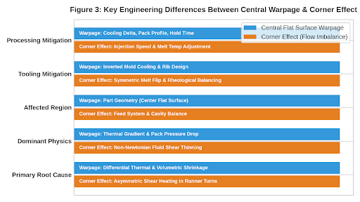
Engineering comparison matrix
| Engineering dimension | Central flat-surface warpage | Runner corner effect |
|---|---|---|
| Primary mechanism | Differential cooling, regional shrinkage, orientation and structural response | Asymmetric shear heating and melt-layer distribution after runner turns |
| Physical domain | Thermomechanics of the molded part | Non-Newtonian flow and heat transfer in the feed system |
| Where it occurs | Part wall, cavity/core surfaces and local geometry | Primary and secondary cold-runner branches |
| Typical evidence | Doming, dishing, twisting or out-of-flatness after ejection | Unequal short-shot fronts, cavity pressure, weight, flash or short shots |
| Mold types affected | Single- or multi-cavity molds, especially broad thin parts | Primarily multi-cavity cold-runner layouts |
| Variables to test | Core/cavity temperature, wall thickness, gate seal, packing and cooling time | Turn sequence, runner shear history, gates, vents and cavity pressure |
| Corrective direction | Balance cooling and shrinkage; improve stiffness and pressure transmission | Reorient or rheologically rebalance melt delivery |
1. What central flat-surface warpage looks like
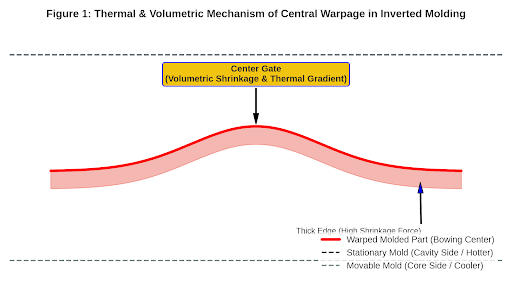
Central warpage appears as a dome, dish or broad bow across a nominally planar surface. It may be visible immediately after ejection or grow as the part reaches room temperature. On a center-gated housing, the center may sit above or below the reference plane while the perimeter remains relatively stable.
Do not diagnose it by direction alone. “The part bends toward the hot side” can be a useful shop-floor clue, but the final direction depends on the combined shrinkage distribution through the thickness and across the plane. Material crystallinity, fiber orientation, local restraint, ribs, wall transitions, packing pressure and ejection temperature can all change the result.
How inverted tooling changes the thermal picture
In a conventional mold, ejection is usually on the moving B-side. In a reverse or inverted arrangement, gating, ejection and cosmetic surfaces may be arranged differently, and the stationary half can receive additional heat from a hot-runner manifold or have less room for cooling. What matters is not the label “A-side” or “B-side,” but the measured temperature field on both faces of the part.
ΔT = Tstationary − Tmovable
A non-zero through-thickness temperature difference creates unequal freezing and contraction histories. The hotter face is not a universal predictor of final bow direction, however, because regional shrinkage, orientation, ribs, constraints and ejection temperature contribute to the same bending response.
Differential cooling
If the cavity and core surfaces remove heat at different rates, the two skins freeze and contract differently. That through-thickness strain becomes a bending moment after the part is released. Autodesk identifies differential cooling as one of the principal contributors to warpage and recommends checking coolant temperature, cooling-line placement and local hot spots. See its explanation of the differential cooling result.
Differential shrinkage and packing
Shrinkage also varies from the gate to the end of fill and between thick and thin regions. A thin section may freeze before hold pressure can compensate it; a thick edge may cool slowly and develop a different crystalline structure. Gate size, gate location, hold pressure, hold time and pressure loss through the part all affect the local specific volume at freeze-off.
A gate-seal study is more useful than simply adding hold time. Increase hold time in controlled steps and record part weight. Once weight stops increasing, the gate is effectively sealed under those conditions. If flatness continues to change beyond that point, cooling, orientation or structural instability deserves more attention.
The thermodynamic link is commonly expressed through the material’s pressure–volume–temperature relationship:
v = f(P, T)
Here, v is specific volume, P is pressure and T is temperature. Regions that freeze at different pressures or temperatures retain different shrinkage potential. For a center-gated panel, the resulting pattern—not simply the highest or lowest local shrinkage value—determines whether the part domes, dishes or forms a saddle shape.
Orientation and structural stiffness
For fiber-filled materials, shrinkage parallel to fiber orientation can differ greatly from transverse shrinkage. Even unfilled polymers develop flow-induced orientation. Meanwhile, a wide thin panel has little bending stiffness; small residual stresses can push it into a stable domed shape. Ribs can improve stiffness, but poorly proportioned ribs may create new thickness and cooling gradients, so they are not an automatic cure.
2. What the runner “corner effect” means
In multi-cavity cold-runner molds, geometrically equal runner lengths do not guarantee equal filling. Polymer melt is shear-thinning: its apparent viscosity falls as shear rate rises. Near the runner wall, high shear generates a hotter, lower-viscosity layer. When that non-uniform melt passes through successive turns and branches, the layers can be distributed unevenly among downstream cavities.
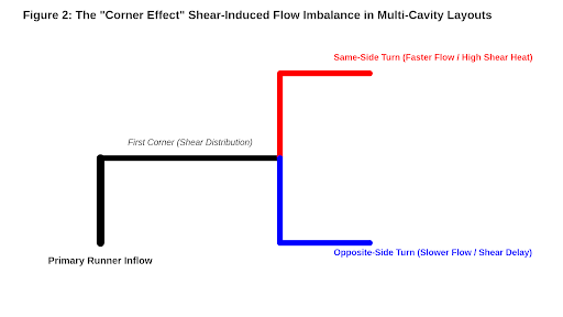
The symptoms are cavity-to-cavity: one cavity reaches end of fill early, flashes first or sees higher peak pressure, while another hesitates or short-shots. Beaumont’s published plastic flow fundamentals describe how melt position and runner branching influence balance and how melt-reorientation concepts can correct the distribution.
Why shear history survives the runner turn
A simple power-law model illustrates shear thinning:
η = K · γ̇n−1, n < 1
In this expression, η is apparent viscosity, K is the consistency index and γ̇ is shear rate. Viscous dissipation increases strongly with shear rate:
q̇shear = τ · γ̇ = η · γ̇2
The runner wall therefore develops a higher-shear, often hotter layer surrounding a cooler core. A turn does not fully remix those layers. Successive branches can direct different portions of that profile toward nominally identical cavities, which is why equal path length alone cannot guarantee equal filling.
This is why a traditional “naturally balanced” H-runner can still behave unbalanced. Geometric balance controls path length and nominal pressure loss; rheological balance must also consider the melt’s thermal and shear history.
3. A diagnostic sequence that separates the two
- Define the metric. Measure flatness on a consistent datum after a defined conditioning time. Separately record cavity fill time, part weight and peak cavity pressure.
- Run short shots. Stop the fill at several transfer positions. If cavities advance unevenly before packing begins, investigate the runner and gate system.
- Compare cavity weights. Persistent cavity-to-cavity weight differences point to melt delivery or gate restriction. Similar weights with different flatness point more strongly to local cooling, orientation or ejection conditions.
- Perform a gate-seal study. Plot part weight against hold time. This establishes whether additional hold can still influence density.
- Map temperatures. Measure cavity and core surface temperatures at repeatable locations after the process stabilizes. An average temperature alone can hide a central hot spot.
- Rotate or swap evidence where possible. If the imbalance follows a runner branch rather than a cavity insert, the feed system is implicated. If it follows the cavity or cooling circuit, investigate local tooling.
- Change one variable at a time. Record fill time, transfer position, cushion, peak pressure, weight and flatness. Multiple simultaneous changes produce a result but rarely a diagnosis.
4. Corrective actions for central warpage
- Balance heat removal: revise cooling-line position, flow rate or circuit layout; remove local hot spots; consider thermally conductive inserts where geometry limits water placement.
- Reduce abrupt wall changes: transition gradually between sections and avoid feeding a large region through a section that freezes too early.
- Improve pressure transmission: verify gate size and gate seal, then develop a packing profile that improves density without overpacking the gate region.
- Review gate location: a gate change alters pressure distribution, weld lines and molecular/fiber orientation, so evaluate it with fill-pack-cool-warp analysis rather than in isolation.
- Control ejection: confirm adequate cooling time, balanced ejection and that the part is not being bent by pins, lifters or manual handling.
- Add stiffness intelligently: use ribs, curvature or section geometry when product design permits, while checking that the change does not create new sink or cooling problems.
Autodesk’s guidance on reducing differential shrinkage emphasizes packing profiles, wall-thickness changes and mold inserts—and, importantly, re-running the full analysis after a design change because the contributors interact.
5. Corrective actions for runner imbalance
- Confirm it with cavity data: short shots and cavity-pressure traces should show where the imbalance begins.
- Review the turn sequence: successive same-direction and opposite-direction turns can distribute the high-shear layer differently.
- Reorient the melt: runner inserts or melt-rotation concepts can redistribute the shear layer before the next branch.
- Rheologically rebalance runners: diameter and geometry changes should be based on non-Newtonian 3D flow analysis, not length alone.
- Check gates and vents: gate machining variation or trapped air can mimic a runner effect and must be ruled out.
- Consider a hot runner where justified: individual drops can improve control, but thermal variation, gate behavior and maintenance remain part of the design.
6. Common troubleshooting mistakes
- Calling every out-of-flat part a cooling problem. Orientation and differential packing can dominate even when mold temperatures look balanced.
- Assuming equal runner length means equal flow. It ignores shear history, temperature distribution, gates and vents.
- Using part weight alone. Equal weight does not prove equal pressure history or equal shrinkage distribution.
- Evaluating parts at inconsistent times. Flatness can change during post-mold cooling and moisture conditioning.
- Changing steel before completing controlled trials. A small DOE around mold temperature, hold profile and cooling time can prevent an expensive but irrelevant modification.
Questions engineers often ask
Can the runner corner effect cause warpage?
Indirectly, yes. Runner imbalance changes the filling and packing history delivered to each cavity. That can produce cavity-to-cavity shrinkage and warpage differences. But it does not explain central bowing in a single cavity by itself; cooling, shrinkage, orientation and stiffness still need to be evaluated.
Does a part always warp toward the hotter mold half?
No. Differential mold temperature can establish a bending tendency, but final direction depends on the complete strain field, including regional shrinkage, orientation, geometry and constraints. Use measured temperatures and isolated-cause simulation instead of relying on a universal direction rule.
What is the fastest shop-floor test?
Run a controlled short-shot sequence and compare each cavity. Unequal advancement before pack is a strong runner/gate clue. If fill is balanced, measure surface temperatures and run a gate-seal/hold-time study while tracking weight and flatness.
What a technical review should contain
A credible review should connect simulation assumptions to physical evidence. At minimum, document the polymer grade and moisture condition, part and runner geometry, fill/pack/cool settings, cavity-specific short shots and weights, core/cavity surface temperatures, gate-seal results, measurement datum and conditioning time. Simulation is most valuable when it is calibrated against this molding data rather than used as a stand-alone picture.
- For central warpage: isolate differential cooling, differential shrinkage and orientation contributions; then compare the predicted deformation mode with measured parts.
- For runner imbalance: use a three-dimensional non-Newtonian model that captures viscous shear heating and the actual turn sequence.
- Before changing steel: confirm the diagnosis with a controlled trial that predicts both the direction and magnitude of improvement.
The engineering takeaway
Start with the symptom, not the label. Central flat-surface injection molding warpage is primarily a deformation problem governed by uneven cooling, shrinkage, orientation and structural response. The cold-runner corner effect is primarily a melt-distribution problem governed by shear history through turns and branches. In multi-cavity molds they can interact, so the reliable method is to separate fill balance from final deformation with short shots, cavity data, temperature measurements and controlled trials.
Rilong Precision Mold supports mold design and tooling, custom injection molding and injection molding defect analysis. For a useful technical review, send the 3D model, material grade, gate and runner layout, molding record, cavity-specific weights, flatness datum and photos of the deformation. Those details allow the engineering discussion to begin with evidence.
Technical note: The diagrams are explanatory sketches. Final corrective action should be based on the actual polymer data, mold construction, process window and measured part behavior.